Offline programming of 12 axes
Offline generated programmes are causing deviations in a cell for welding very large assemblies.

Advantages
Benefit for the client
The accuracy of the entire 12-axis system, consisting of a gantry robot, tool and 3-axis positioner, has been significantly improved. A test with an off-line generated programme resulted in an improvement in overall accuracy of several centimetres to 1.5mm.
The measurement with LaserLAB and loop:in takes less than 5 minutes and can be repeated by the customer at any time. As a result of the calibration, loop:in moves the robot and portal axes to the fine calibration positions. The customer simply performs a fine calibration of all axes at this position.
If the calibration is lost, the customer can automatically calibrate all axes. Previously, he had to use an extra riser to move the portal axles to their adjustment positions at a height of about 3 metres.
Measurement under 5 minutes
Increasing the accuracy of the cell
Any number of repetitions of the measurement
Fully automatic calibration without the use of risers
Case
Cell description
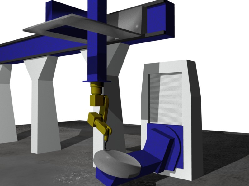
The installation consists of an ABB IRB 2400 suspended from an XYZ gantry. The gantry has a travel path of approximately 8 m x 3 m x 3 m. Very large assemblies – such as excavator buckets or crane parts – are welded using the MIG/MAG welding process on a 3-axis positioner consisting of a turn/swivel unit combined with a lifting unit.
Task
In some cases, the customer produces batch sizes of as little as one piece on the line. This means that robot programmes have to be created individually for each component. In a normal teach-in process, this would mean that no production could take place on the line during this time.
In addition, teaching a twelve-axis system is extremely difficult and tedious. The optimal welding paths can be determined much better and faster on a CAD system than with the teach-in process.
The customer’s problem was that the off-line generated programmes resulted in deviations of up to 30 mm on the real cell. This is partly due to the lack of absolute accuracy of the robot and gantry system, and partly to the fact that the geometric relationship between the gantry and the positioner could only be determined imprecisely using the robot manufacturer’s standard methods.
Implementation
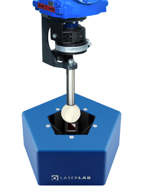
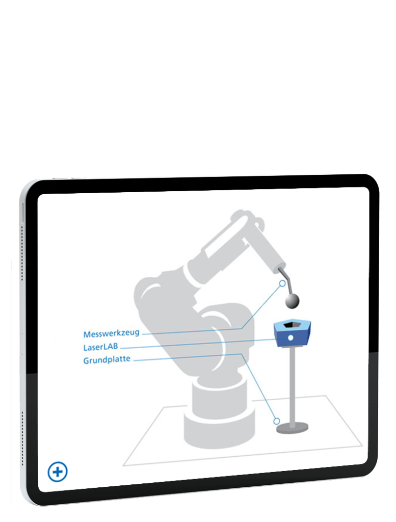
A base plate was attached to one of the gantry columns and the LaserLAB was flanged to it. A measuring rod with a measuring ball was screwed into the welding torch instead of the contact tip. The measuring rod is designed so that the centre of the measuring sphere corresponds to the working point of the welding wire (TCP). With the LaserLAB and the loop:in software, all the robot axes and the axes of the XYZ gantry were now automatically controlled so that the measuring sphere always remained in the centre of the LaserLAB. Approximately 30 measurements were taken in this way, from which the optimum values for fine calibration of the robot were determined.
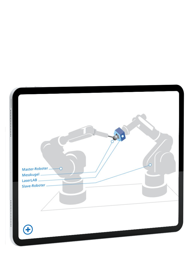
In a second step, the geometric relationship of the additional axes (positioners) to the portal was determined. For this purpose, the LaserLAB was flanged off-centre to the rotary axis of the positioner. The position of the LaserLAB has now been measured at twelve different positions using the absolute-precision system consisting of gantry, robot and measuring sphere. It was important to move the additional axes to as many different positions as possible.
The survey is carried out using a semi-automatic procedure. The software kir:in is used. The result of the calibration is stored by kir:in in the moc.cfg file loaded in the robot.
Products
The solution can be implemented with these products

LaserLAB
The ultimate all-in-one solution for robotic cell measurement and calibration tasks
Technical support
Contact our support team with any technical questions.
+49 (0)821 123 456
Technical support
Contact our support team for all technical questions
+49 (0)821 123 456
More cases
Here you can find more cases on this topic
Fast commissioning of offline programmes
Fast commissioning of offline programmes In order

