Optimised set-up time and fast post-crash maintenance
The customer operates several XY portals with Motoman HP20 robots and NX100 controller. This is where the MIG/MAG welding process is used to weld together the frame panels. These are used for scaffolding. The frames are clamped onto fixtures and these are staked onto a positioner in the robot cell.

Advantages
Benefit for the client
After a crash or to check the robot, the customer can master all 6 robot axes and the two gantry axes in just 20 minutes. There is no need for a ladder to access the portal axles.
After changing the fixture, the new fixture is quickly and accurately measured using the robot and LaserLAB, and is no longer measured.
Thanks to the ease of use of the LaserLAB, the customer will be able to carry out the measurement of his own fixtures step by step.
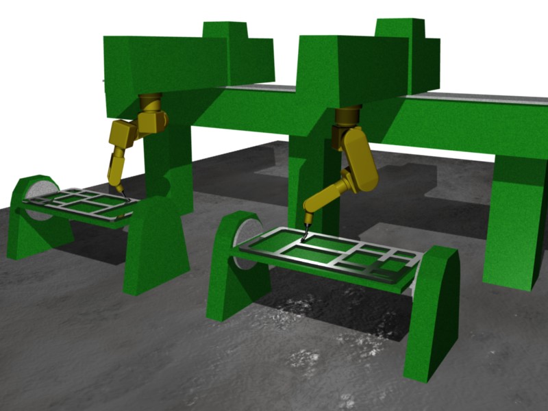
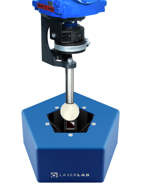
Offline programming possible
A point offset is excluded
Absolutely accurate measurement through loop:in
No problems with old KR6 robots
Case
Cell description
The customer has a production line in its paint shop in which PVC is applied as underbody protection to the underbody of the car body. The system features 12 KUKA KR16 robots on linear axes, equipped with SCA Schuker spray lances with three nozzles each. In the seam sealing line, there are four old Kuka KR 6 robots that can only be adjusted via nonius.
Task
The initial task was to develop a method to quickly and automatically control the robot and the gantry axes. The customer is experiencing relatively frequent crashes with their robots, resulting in incorrect robot or gantry axis control. The subsequent calibration with the electronic probe offered by Motoman takes 1 to 2 hours. This time should be significantly reduced.
The second task we were given was to reduce set-up times. The fixtures measure 2.5m x 1.5m and are lifted into the positioner by forklift. However, the clamping of the fixtures is relatively imprecise, which meant that each time the fixture was changed, the robot programme had to be repositioned and taught again. The smaller the batch sizes of the parts produced, the more important it is to optimise set-up times.
Implementation
A base plate was attached to one of the gantry columns and the LaserLAB was flanged to this. A measuring rod with a measuring ball was screwed onto the welding torch instead of the contact tip. The measuring rod has been aligned so that the centre of the measuring sphere corresponds to the working point of the welding wire (TCP). With the LaserLAB and the loop:in software, all the robot axes and the axes of the XY portal were now automatically controlled so that the measuring sphere always remained in the centre of the LaserLAB. Around 30 measurements have been taken from which the optimum robot control values were determined.
In a second step, 4 fitting holes were made on a fixture to hold the measuring rods. The robots are equipped with a quick-change system. The torch can be quickly removed and replaced with a LaserLAB holder. With a taught-in robot programme, the 4 measuring rods are now measured with the robot and the LaserLAB. The result of the measurement is a so-called user coordinate system, which is transmitted directly to the robot. The accuracy with which the new position of the fixture was measured was a maximum of 0.4 mm.
Products
These Wiest products were used:

LaserLAB
The ultimate all-in-one solution for robotic cell measurement and calibration tasks
Technical support
Contact our support team with any technical questions.
+49 (0)821 123 456
Technical support
Contact our support team for all technical questions
+49 (0)821 123 456
More cases
Here you can find more cases on this topic
Fast commissioning of offline programmes
Fast commissioning of offline programmes In order